


Product Introduction
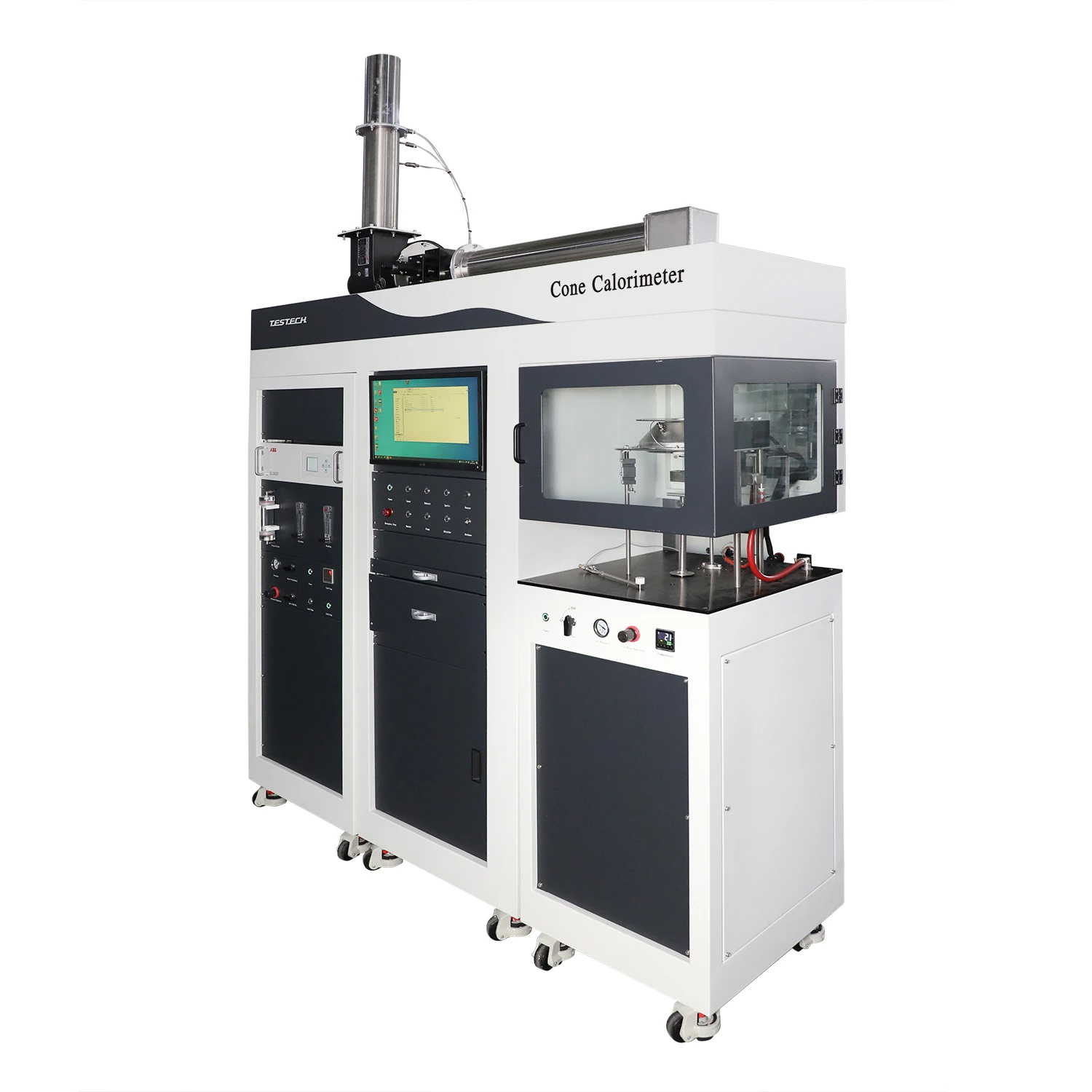
Heat release is a core measurement parameter for evaluating the fire characteristics of materials and products. The cone calorimeter complies with all existing standards, including ISO 5660, ASTM E1354, ASTM E1474, ASTM E1740, ASTM F1550, ASTM D6113, NFPA 264, CAN/ULC 135, and BS 476 Part 15.
It can also be purchased in modular form. If a laboratory only needs specific tests at first, such as heat release, mass loss, or smoke generation, the required components can be purchased first. Other instruments can then be gradually added to the same test chamber to form a complete full-specification system. This flexibility is one of the many advantages of this cone calorimeter.
The testing principle of the cone calorimeter is based on the fact that the heat of combustion is proportional to the amount of oxygen consumed. For every 1 kg of oxygen consumed during combustion, 13.1 MJ/kg of heat is generated. The system measures heat release, ignition time, oxygen consumption rate, CO and CO₂ generation rates, and combustion gas flow.
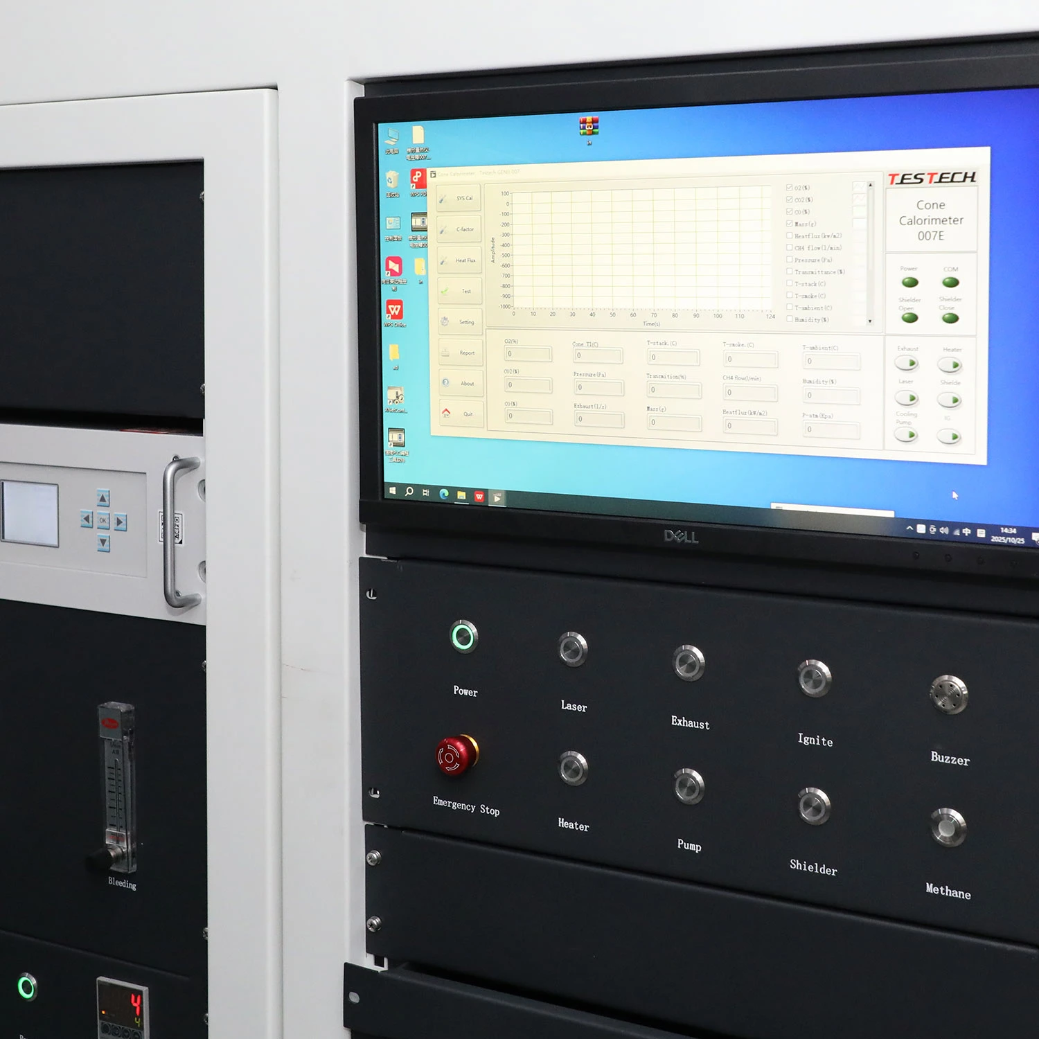
The DAQ system of the cone calorimeter helps users easily control the entire test. The 19-inch touch screen enables test automation and reduces installation space. In addition, after users set the virtual temperature corresponding to real fire conditions, testing can be performed by changing the specimen temperature and temperature rise time. This method can produce test results similar to those obtained under real fire conditions.
Product Model: FTech-ISO5660
Applicable Standards
ISO 5660: Reaction-to-fire tests - Heat release rate, smoke production rate, and mass loss rate
ASTM E1354: Standard Test Method for Heat and Visible Smoke Release Rates for Materials and Products
BS 476 Part 15: Fire tests on building materials and structures - Method for measuring the rate of heat release of products
GB/T 16172-2007: Test method for heat release rate of building materials
NFPA 264: Measurement of heat release rates of materials and products using an oxygen consumption calorimeter
1. Structural Features
1.1 Standard control cabinet with computer + LabVIEW intelligent control system; elegant appearance and easy operation.
1.2 Cone heater: truncated cone design, 230 V, 5000 W, heat output range of 0–120 kW/m².
1.3 Automatic ignition system with automatic combustion time measurement.
1.4 Temperature control using three K-type thermocouples and three PID temperature controllers.
1.5 Automatic movable radiation shield: protects the specimen area before testing, ensures stable initial mass measurement, and gives the operator extra time to check the system before the test begins. For easily ignitable specimens, premature ignition may occur if there is no opening/closing mechanism, making this extra time very important for the operator.
1.6 Specimen holder: specimen size 100 mm × 100 mm, thickness not exceeding 50 mm; the exposed central area of the specimen is 50 mm × 50 mm, with deviation from the cone heater center within ±1%.
1.7 Weighing system: imported Siemens load cell. Mass is measured by a strain-gauge load cell with accuracy up to 0.1 g. Mechanical stops prevent damage caused by movement, ensure stable results, and extend instrument service life. Weighing range: 0–3 kg.
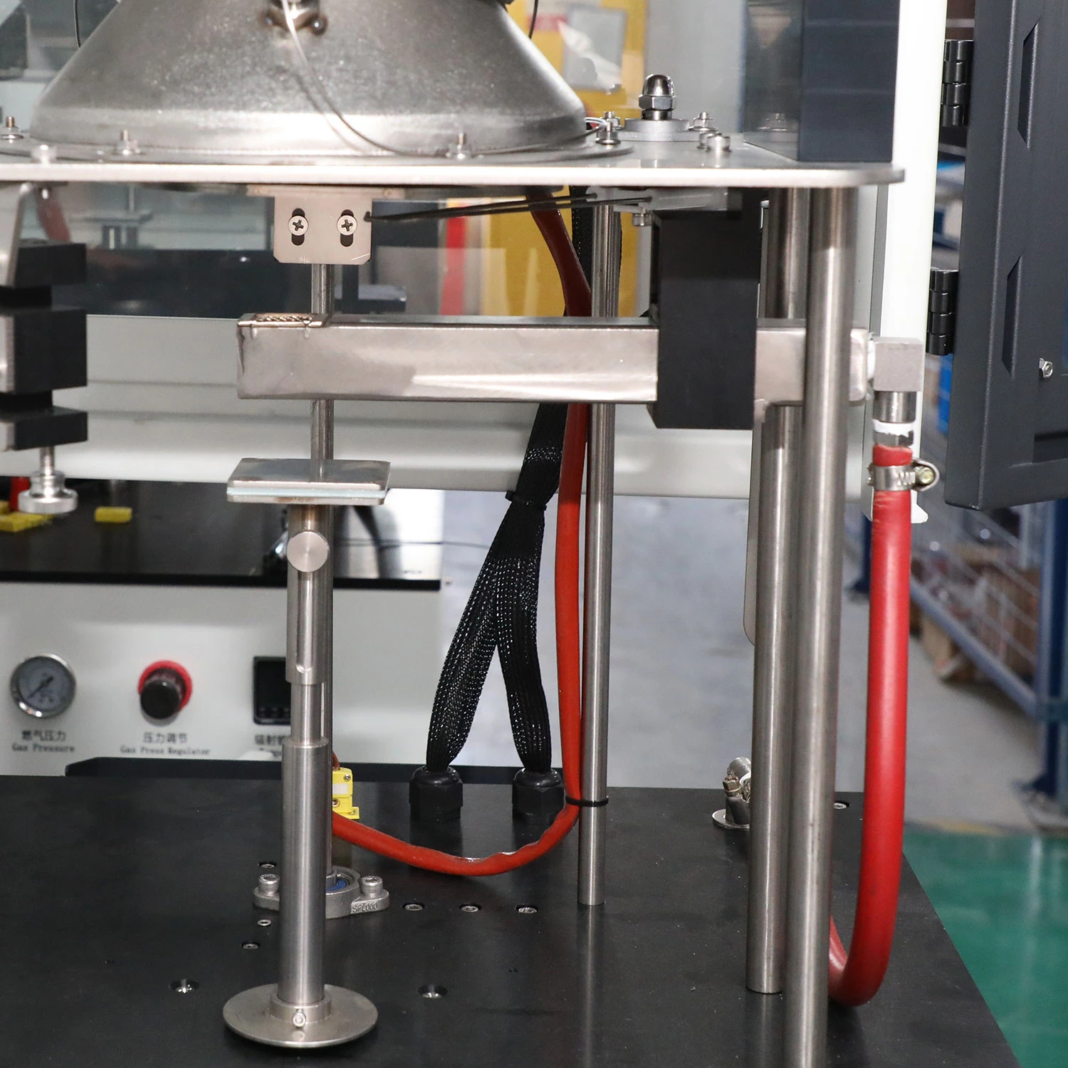
1.8 The radiation cone and weighing system are placed on an independent workbench and are not connected to the main test unit, preventing vibration from fan ducts from affecting weighing accuracy.
1.8 Independent data analysis cabinet, movable and usable for other heat release experiments.
1.9 Flexible connection between the cone heater and weighing system avoids weighing errors caused by vibration from fans, water pumps, and other equipment.
2. Ignition System
2.1 Spark generator above 10 kV with safety shut-off device. The ignition timer supports segmented timing, with display resolution of 1 s and timing error less than 1 s/h. The burner calibration flowmeter accuracy shall be ±2% of reading.
2.2 Automatic ignition, automatic timing, and automatic gas shut-off/flame extinguishing.
2.3 Imported lens and filter. The laser and photoelectric receiver are isolated from smoke gas.
2.4 The laser/laser unit and smoke duct are designed separately to prevent smoke duct vibration from affecting the optical system.
3. Exhaust System
3.1 Composed of axial-flow fan, stainless-steel smoke exhaust duct, diffuser plate, smoke collection hood, exhaust pipe, orifice flowmeter, and thermometer.
3.2 Made of stainless steel for extended service life, including hood, gas sampling probe, and exhaust fan.
3.3 Smoke exhaust air velocity control: air velocity 24 L/s; adjustable flow from 0 g/s to 50 g/s, with minimum accuracy of 0.1 g/s and error of 1%.
3.4 Equipped with orifice flowmeter and imported micro differential pressure sensor. Range: 0–500 Pa; accuracy: ±1.0% FS; hysteresis: ±0.1% FS; non-repeatability: ±0.05% FS.
4. Gas Sampling System
4.1 Includes annular sampler, suction pump, particle filter, cold trap, exhaust valve, moisture filter, and CO₂ filter.
4.2 Three-stage filtration system; filtration accuracy: 0.3 μm.
4.3 Refrigerated cold trap using compressor air-conditioning refrigeration system; controlled temperature: 0–5°C.
4.4 Imported suction pump; flow rate: 33 L/min; vacuum: 700 mmHg; pressure: 2.5 bar.
4.5 Drying cylinder for filtering moisture and impurities.
4.6 Flow controller for controlling suction flow.
4.7 The sampler has 12 small holes facing opposite the airflow direction, with built-in soot filter, positioned 685 mm from the smoke collection hood.
5. Measurement System
5.1
Oxygen concentration analysis: Imported-brand or equivalent paramagnetic oxygen analyzer, O₂ measuring range 0–25%, linear deviation <0.5% of range, repeatability <50 ppm O₂. Analyzer response time: T90 <3.5 s. Domestic analyzer is optional.
CO₂ analysis: Imported-brand or equivalent infrared CO₂ analyzer, measuring range 0–10%, linear deviation ≤1% of range, repeatability ≤0.5% of range. Analyzer response time: T90 <2.5 s.
CO analysis: Imported-brand or equivalent infrared CO analyzer, measuring range 0–1%, linear deviation ≤1% of range, repeatability ≤0.5% of range. Analyzer response time: T90 <2.5 s.
5.2 Imported laser system for smoke density measurement, accuracy error: 2%; uses photodiode, 0.5 mW helium-neon laser, main and backup photodetectors.
5.3 Imported photoelectric receiver from the United States: wavelength range 350–1100 nm, peak response 0.65 A/W, gain adjustment 70 dB.
5.3 Imported load cell measures specimen mass change during testing through a high-precision weighing sensor. Test range: 0–3000 g; resolution: 0.01 g. Actual specimen mass requirement: <500 g.
5.4 Temperature control system: imported Omron PID temperature control system; three thermocouples with diameter of 1 mm measure cone temperature; one 1 mm sheathed thermocouple is used in pairs to measure temperature 100 mm above the orifice plate.
5.5 Imported Omega thermocouple from the United States, accuracy 0.1°C, fast temperature acquisition, and durable service life.
5.6 Exhaust flow is calculated from the pressure difference across both sides of a sharp-edged orifice plate with an inner diameter of 57 mm ± 1 mm in the smoke exhaust duct, together with a micro differential pressure transmitter. It is connected to the control system to realize automatic air velocity control and is located 350 mm above the fan.
5.7 Imported micro differential pressure sensor from the United States; accuracy: ±1% FS; hysteresis: ±0.1% FS; maximum linear pressure: 69 kPa.
6. Calibration System
6.1 Imported Metherm thermopile heat flux meter from the United States, used to set the radiation level on the specimen surface. Equipped with a water-cooling system to protect the heat flux meter. Designed range: 0–120 kW/m²; heat flux meter accuracy: ±3%; repeatability: ±0.5%.
6.2 Burner calibration system: calibrates the measured heat release rate using methane with 99.5% purity. A methane mass flowmeter precisely controls methane flow.
6.3 Equipped with a water-cooling system for cooling the imported heat flux meter during operation. Both self-circulating water tank and tap-water connection modes are available; customer selectable.
6.4 Equipped with square calibration burner.
6.5 Imported mass flow controller from Japan; flow accuracy: 2%.
7. User Operation System
7.1 Dedicated LabVIEW control system for laboratory instruments, with user-friendly interface, easy operation, and precise control. It can display instrument status, calibrate instruments and store calibration results, collect test data, calculate required parameters, display results according to standard requirements, and average multiple test values.
7.2 The host computer communicates with the programmable controller through an RS485 communication module for data transmission and action control.
7.3 The PID temperature control module is linked to the power adjustment module, and constant-temperature regulation is performed through programmable controller control.
7.4 The signal acquisition and processing module is linked to the airflow circuit control module. Through programmable controller logic calculation output, the preset air velocity is intelligently adjusted. The mechanical rotation module is connected to the I/O port of the programmable controller to control the closed state of the rotating mechanism.
7.5 LabVIEW operating software has a friendly interface and strong data interaction capabilities, making it more suitable for scientific research and analysis.
7.6 Modular software design allows independent analysis of process curves for each test dataset.
7.7 Through parameter settings, raw test data can be revised, and differences in test results for the same specimen can be compared. This helps customers analyze influencing factors in experiments.
7.8 Test reports support switching between full-size charts and thumbnail views for analysis.
7.9 Delay times for O₂, CO, and CO₂ can be independently revised, enabling comparison of test results and deeper analysis of experimental data.
7.10 Users can freely select data output curves: O₂, CO₂, CO, MASS, Heatflux, MFM, DPT, and PD.
7.11 Highly integrated automatic system operation; C-factor and test functions can be operated with one click.
7.12 Powerful test report module, supporting preview, editing, and report generation.
7.13 C-factor log records system C-factor calibration data and monitors system changes.
7.14 Heatflux log records radiant heat flux power setting data for easy reference.
7.15 Test results are accurate and reliable, with good repeatability and error not exceeding ±2%.
7.16 Delay time can be tested and analyzed.
8. Technical Parameters
8.1 Cone heater rated power: 5000 W; heat output: 0–120 kW/m². Radiation irradiance is uniform, with deviation from center irradiance not exceeding ±2%. Heat flux meter accuracy: ±3%; repeatability within ±0.5%.
8.2 Specimen weighing range: 0–3000 g. Independent weighing device with sensitivity of 0.1 g. Output drift of weighing equipment does not exceed 0.8 g within 30 minutes. The cone heater test frame is completely separated from the main test unit frame to avoid vibration effects on the weighing system. Flexible connection between cone heater and weighing system avoids weighing errors caused by vibration from fans, water pumps, and other equipment.
8.3 Specimen holder: specimen size 100 mm × 100 mm, thickness not exceeding 50 mm; exposed central area of specimen is 50 mm × 50 mm, with deviation from cone heater center within ±1%.
8.4 Imported paramagnetic oxygen analyzer; oxygen range 0–100%, error <0.01%, repeatability <0.01%, response time <5 s.
8.5 Infrared CO and CO₂ analyzers: CO₂ range 0–10%, error 1% FS, repeatability <2%, response time <7 s; CO range 0–1%, error 1% FS, repeatability <2%.
8.6 Exhaust fan with adjustable flow of 0–50 g/s, accuracy 0.1 g/s.
8.7 Compressor-based cold trap: 0–5°C.
8.8 Imported diaphragm pump, flow rate: 33 L/min.
8.9 Micro differential pressure sensor: range 0–500 Pa; accuracy ±1.0% FS; hysteresis ±0.1% FS; non-repeatability ±0.05% FS.
8.10 Imported thermopile heat flux meter, designed range 0–120 kW/m²; heat flux meter accuracy ±3%; repeatability ±0.5%.
8.11 Detector chromaticity standard accuracy ±5%; output linearity, transmittance, <1%; absolute transmittance <1%.
8.12 Imported micro differential pressure sensor from the United States; accuracy ±1% FS; hysteresis ±0.1% FS; maximum linear pressure 69 kPa.
8.13 Imported photoelectric receiver from the United States: wavelength range 350–1100 nm; peak response 0.65 A/W; gain adjustment 70 dB.
8.14 During calibration, the average temperature of the cone thermocouples shall be maintained within ±5°C of the preset value.
9. Test Data
9.1 Heat release rate, total oxygen consumption, and CO₂ generation.
9.2 Ignition time, flue gas flow velocity, C-factor, and extinction time.
9.3 Critical ignition heat.
9.4 Mass loss rate.
9.5 Smoke release rate.
9.6 Total heat release.
9.7 Analysis of the influence of time lag on test results.
Optional Items
Independent ISO 5660-4 Large Cone Test Bench
The large cone heater complies with the design requirements of ISO/TS 5660-4 and ASTM E2965. It can be used for testing specimens measuring 150 mm × 150 mm.
Parameter Introduction
Independent movable test platform. It can be used interchangeably with the ISO 5660-1 standard test bench, enabling multi-standard and multifunctional use of the cone calorimeter.
The large cone heater has a total power of approximately 15 kW, lower outer diameter of approximately 350 mm, and top outer diameter of approximately 150 mm.
Cone heater irradiance can reach 80 kW/m².
Metal reflective upper surface shield and composite insulation shield effectively isolate the specimen from the influence of the radiation cone before the experiment begins.
Weighing system accuracy: ±0.1 g; weighing range: 3 kg. The 10%–90% response time of the weighing device is less than 4 s. Drift within 30 minutes does not exceed 1 g.
Square specimen holder: top external dimensions are 156 ± 1 mm × 156 ± 1 mm, depth 25 ± 1 mm. Made of stainless steel with thickness of 2.5 mm.
Specimen clamp cover, stainless steel: thickness 1.9 ± 0.1 mm, internal dimensions 161 ± 1 mm, height 54 ± 1 mm. The opening of the specimen surface shall be 144.0 ± 0.5 square millimeters.
Smoke exhaust system with adjustable air velocity according to different standards. The test airflow rate is 0.018 m³/s.
Independent ISO 5660-5 Air Environment Control Test Bench
This test device complies with ISO 5660-5 for heat release testing under adjustable air/oxygen concentration conditions. The method provides a controlled environment for evaluating the combustion reaction of tested products under different oxygen concentration environments. The specimen is simultaneously exposed to radiant heat irradiance of 0–50 kW/m².
For testing specimens in low-oxygen atmospheres of 0–21%, this TTech system exceeds the standard requirements. It can also provide combustion heat release testing under oxygen-enriched conditions, with oxygen concentration greater than 21%, to meet diverse scientific research needs.
Parameter Introduction
Independent movable test platform. It can be used interchangeably with the ISO 5660-1 standard test bench, enabling multi-standard and multifunctional use of the cone calorimeter.
Provides an independent combustion chamber with variable air environment. A customized circular cone heater is integrated into the upper end of the combustion chamber.
The combustion chamber integrates the specimen platform, weighing platform, shield, igniter, and other test devices.
The combustion chamber is equipped with a large observation window for convenient observation of internal combustion conditions.
The combustion chamber is equipped with an openable door for convenient internal operation and specimen installation.
The combustion chamber provides a controlled oxygen concentration combustion test environment through imported air and oxygen mass flow controllers.
Mass flowmeter range: 0–200 L/min, accuracy 2%; total inlet airflow into the environmental chamber: 150–180 L/min.
Equipped with imported oxygen sensor for monitoring oxygen concentration inside the environmental chamber.
Metal reflective upper surface shield and composite insulation shield effectively isolate the specimen from the influence of the radiation cone before the experiment begins.
Weighing system accuracy: ±0.1 g; weighing range: 3 kg. The 10%–90% response time of the weighing device is less than 4 s. Drift within 30 minutes does not exceed 1 g.


