


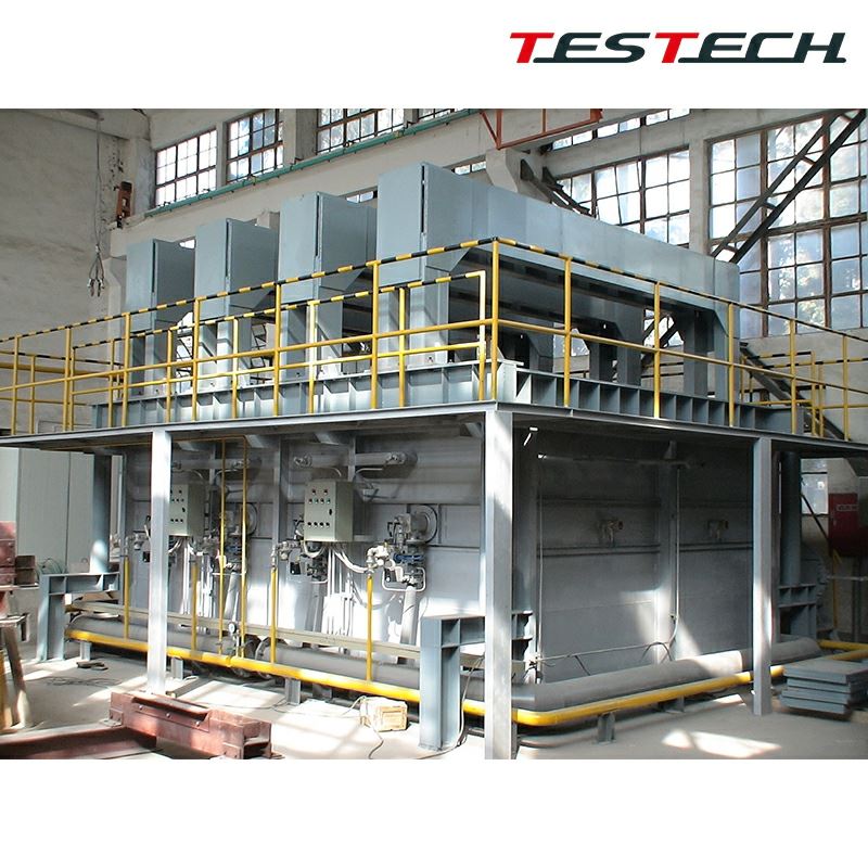
TESTech Instrument (Suzhou) Technologies is one of the leading manufacturers and suppliers of fire resistance horizontal test furnace in China. Welcome to wholesale premium test equipment at competitive price from our factory. If you have any enquiry about quotation, please feel free to email us.
Equipment Overview
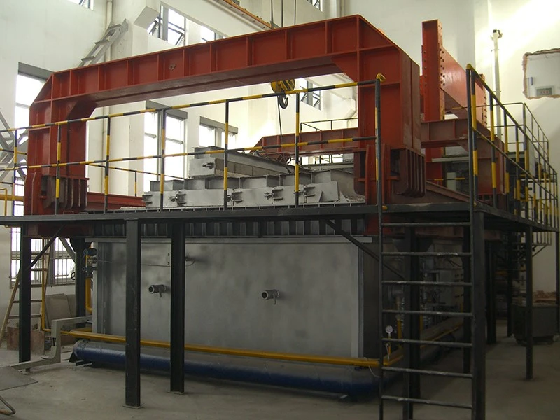
The horizontal fire resistance test furnace is used to test the fire resistance performance of horizontal building structures, columns, supports, and similar assemblies.
It can quantify high-temperature resistance performance through testing of load-bearing capacity, fire suppression behaviour, and thermal conductivity of materials.
The furnace design complies with the relevant requirements of EN 1363-1, EN 1363-2 hydrocarbon curve, and ISO 834 for fire resistance testing of building material components, and is similar to applicable national requirements.
The equipment has been specially designed and improved over many years to provide a reliable and accurate method for testing various specimen configurations with the necessary combustion chamber components.
The equipment evaluates the specimen response to heating under specified time, temperature, and pressure conditions according to defined performance criteria.
The furnace is manufactured, lined, and tested in the factory, then dismantled into transportable parts for trailer shipment according to the preset functional configuration.
The furnace wall is finished with heat-resistant paint and the piping system is configured according to current regulations. The test temperature can reach up to 1250 degrees C.
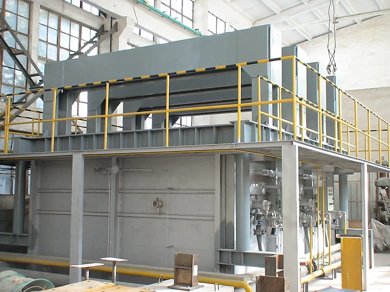
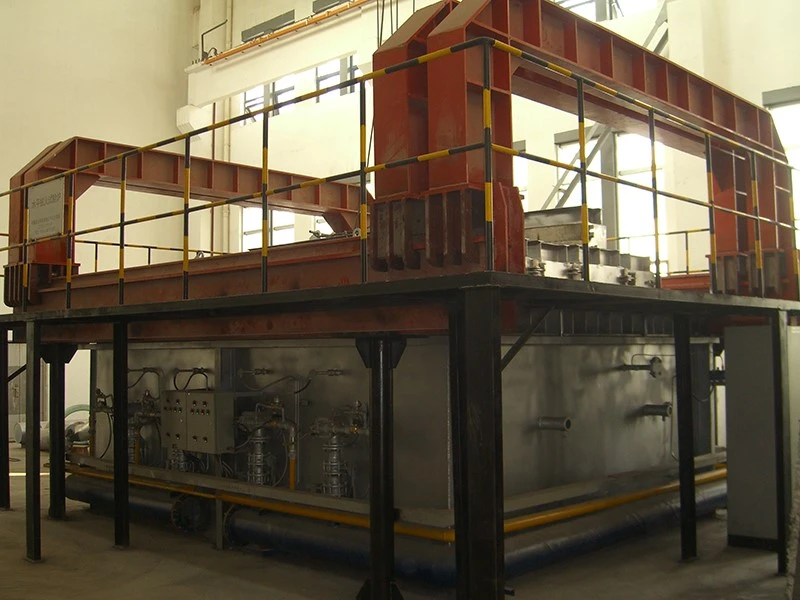
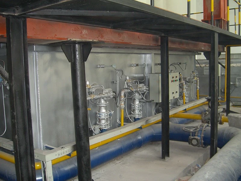
Structural Features
- Fire resistance test furnace with test area dimensions of 3000 mm (W) x 4000 mm (H) x 1000 mm (D).
- Lined with 1400-grade insulating brick, refractory cast blocks, and mineral wool board. The furnace roof is laid with special-shaped bricks and lined in situ with refractory material.
- A non-deforming access door is positioned in one end wall of the furnace, fully lined, hinged, and clamped to provide access into the furnace.
- Diatomaceous earth insulation and ultra-insulating low-temperature materials are used in certain areas, while 42% dense alumina refractory bricks are used where suitable for cemented joints and hazardous areas, providing sufficient insulation during a 6-hour high-temperature test.
- Capable of carrying out non-load-bearing testing of horizontal test specimens fixed to a custom fixing frame.
- High-efficiency and safe structure with refractory cold-face lining made of refractory insulating brick, cast refractory blocks, and mineral wool board, while the hot face is lined with refractory insulating brick.
- Movable furnace roof with special-shaped bricks and in-situ refractory lining.
- Furnace casing made of low-carbon steel plate reinforced with C-channel steel and I-beams to address thermal deformation and provide a strong non-deforming structure.
- Specimen fixing frame mounted on the furnace front and fixed by four sets of clamps.
- Four observation ports on one long furnace wall, fitted with heat-resistant quartz glass for observation of the specimen during testing.
- Air-cooled insulated frame with lightweight aluminum fiber sliding doors to cover the observation ports when not in use.
- Heat-resistant nozzle mixing burners using liquefied petroleum gas, equipped with flame monitoring, complete flame safety systems, interrupted ignition system, and temperature sensors.
- Burner control panel supports both fully automatic and manual modes. Automatic ignition follows preset heat curves such as BS 476 Parts 20-24, EN 1363, and IMO hydrocarbon curve. Manual control can ignite specified burners individually.
- Three circular flue drain sections, each containing an air lock made of high-grade stainless steel with water-cooled shafts. Flue lining in this area uses biodegradable ceramic fiber material.
Technical Features
- Thermocouples, positions, and design comply with the latest regulations. Nine thermocouple positions are specified in the rear furnace wall, and suitable nickel-iron alloy tubes are supplied to support the provided thermocouples.
- Pressure points, positions, and design comply with the latest regulations. Two nickel-iron alloy pipes are placed on each side of the combustion chamber wall with T-shaped ends, and all pressure points are connected to the field-wired inverter.
- LPG industrial high-temperature luminous soft-flame burners are installed in upright position, with six burners on each side wall of the furnace, complete flame safety systems, interrupted ignition system, and temperature sensors.
- Precast high-temperature refractory blocks arranged in stainless steel frames form the high-temperature lining of the specimen lifting frame and fixing frame. An additional lifting frame with two side hooks is provided for moving the specimen frame into the furnace.
- The chimney is made of low-carbon steel, with the first 6 m provided with high-temperature lining. It extends at least 3 m above the furnace roof and can be designed according to required specifications.
- The combustion air supply blower system is pre-extracted and tested before gas delivery.
- The system is equipped with nine K-type thermocouples, one plate thermocouple, one pressure gauge, and one ambient-temperature thermocouple assembly.
- Four observation ports are located in the furnace rear wall, consisting of heat-resistant glass, air cooling, connected supply pipes, and stainless steel insulation plates. A camera shutter can be used as an alternative.
- Electric pressure-control air locks allow gases to enter through three openings into the vertical duct at the back of the furnace and then into a common ground flue. These air locks are motor-driven and water-cooled, with customer-supplied water and drainage.
- All solenoid valves, safety control boxes, spark plugs, flame detectors, negative and over-pressure switches, motorized valves, and safety interlock limit switches are connected by the installation engineer to the field-wired terminal box.
- PLC and computer control use Siemens PLC CPU and Siemens-compatible remote I/O. Fire test data management software is written according to customer requirements and can be preprogrammed with other standard time-temperature curves.
- The PLC controller includes a built-in operating interface, recording and programming capability, and necessary motor starters. The system can display the real-time heating curve and real-time boiler control system status on the computer screen.
- A dual-recording data logging system records data on the computer, displays real-time analysis data during the test, can distribute the screen over a standard computer network, and automatically saves all recorded information to another computer.
- The furnace can also be operated manually. The complete ignition system does not depend on the control computer. Burners can be ignited via manual clearing and starting sequence, with individual control of gas-air positions and air-lock motors. Sound alarm equipment is also installed.
Technical Specifications
| Test Area Dimensions | 3000 mm (W) x 4000 mm (H) x 1000 mm (D) |
| Maximum Furnace Temperature | 1250 degrees C |
| Input Channels | 240 total, bipolar differential |
| Connector Type | 4 mm round socket, two per channel |
| Input Range | DC voltage, 5 mV, 50 mV, 500 mV, 5000 mV, software programmable |
| Basic Resolution | 21 bit |
| Computer Interface | RS485 multipoint 75 ohm twisted pair |
| Power Supply | 200-240 VAC or 100-130 VAC or 24 VAC, 40-70 Hz |
- Basic accuracy: 0.005% FS.
- Measurement speed: 1 ms to 3 s, software programmable.
- Cold-junction compensation: absolute compensation +/- 0.1 degrees C.
- Power consumption: 7 VA.
Additional Notes for Thermal Insulation Efficiency Test of Components
Furnace Cover Design for Steel Structure Fireproof Coating Insulation Efficiency Test
- An adjustable furnace cover structure is designed to meet the specimen size requirements of the insulation test, suitable for 3 to 8 specimens of 500 mm x 500 mm x (6 to 10) mm.
- The exposed coated surface shall be flush with the lower surface of the furnace cover, and all gaps between the perimeter of each specimen and the installation frame shall be filled with aluminum silicate fiber wool.
- The exposed fire area of each specimen shall be not less than 450 mm x 450 mm.
- The furnace cover reserves installation space for aluminum silicate fiber blanket and thermocouple fixing devices.
- The remainder of the furnace body structure follows the description of the fire resistance test section.
Furnace Temperature and Pressure Control
- The furnace temperature and furnace pressure conditions shall comply with the provisions of GB/T 9978.1.
Control System for Component Insulation Test
- Independent control system for component insulation testing.
- Independent operating interface, control logic, and calculation program for the component insulation test.
Hot Tags: fire resistance horizontal test furnace, China fire resistance horizontal test furnace manufacturers, suppliers, factory, building material fire tester, cone calorimeter, flame retardant building material tester, heat release rate tester, radiant panel flame spread tester, spread of flame tester


