


TESTech Instrument (Suzhou) Technologies is one of the leading manufacturers and suppliers of difficult-flammability of building materials tester in China. Welcome to wholesale premium test equipment at competitive price from our factory. If you have any enquiry about quotation, please feel free to email us.
Product Overview
The TESTech difficult-flammability testing furnace satisfies the technical indexes and requirements specified in GB/T 8625-2005.
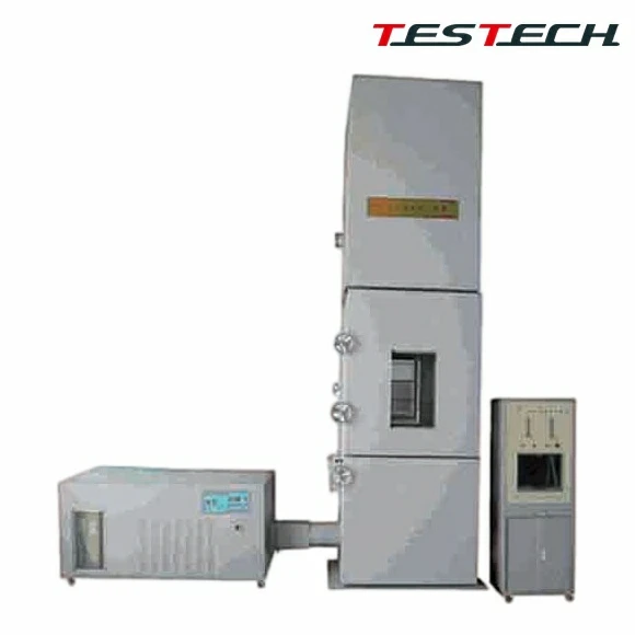
The test apparatus mainly consists of two parts: a vertical combustion furnace and test equipment.
It is suitable for determining the difficult-flammability of building materials and is mainly used in the construction industry or by quality supervision departments. Materials that pass the furnace test and the building material combustibility test can be classified as difficult-flammable building materials.
Structural Features
- The combustion furnace is made of stainless steel for resistance to burning corrosion.
- The vertical combustion furnace mainly consists of compressed air system, combustion chamber, burner, specimen holder, airflow stabilizing layer, and flue; overall dimensions are 1020 mm x 1020 mm x 3930 mm.
- The combustion chamber is formed by furnace walls and furnace doors, with internal dimensions of 800 mm x 800 mm x 2000 mm and an insulated sandwich wall structure; observation windows are provided on the upper door and rear wall.
- The furnace doors are divided into upper and lower sections, hinged to the furnace body and closed by handwheel and fixing screw rod.
- The airflow stabilizing layer is a stainless steel frame below the burner, with wire mesh at the bottom and multiple layers of fiberglass pads on top.
- The flue is a square duct with cross-sectional area 500 mm x 500 mm, located at the top of the furnace and connected to the external chimney.
- Air is supplied at constant rate through a 200 mm diameter duct at the lower part of the furnace body.
- The air stabilizer is arranged below the burner, with wire mesh at the bottom and fiberglass felt above.
- Test equipment includes high-performance flowmeter, thermocouples, temperature recorder, temperature display instruments, and furnace pressure measuring instruments.
- All corrosion-resistant fittings and supports are made of stainless steel.
Control System
- Temperature measurement uses microcomputer display and recording, with testing accuracy of 1 C.
- Thermocouples are armored nickel-chromium thermocouples of Class II accuracy, with five groups provided.
- Additional nickel-chromium/nickel-silicon sheathed thermocouples of Class II accuracy are used, with wire diameter 0.5 mm and outer diameter not greater than 3 mm.
- Furnace pressure measurement uses a differential pressure transmitter of Class 0.5 accuracy and communicates with the PLC and microcomputer control system.
- Methane and air flowmeters have accuracy not less than Class 2.5 and range 0.25-2.5 m3/h.
- System control uses a PLC plus touch screen microcomputer control system.
- The exhaust system uses a powerful fan to remove waste gas after the test is completed.
- Ignition is by high-voltage automatic ignition system.
- Test data is automatically collected and stored, and test reports are automatically generated.
- Remote printing of data can be realized.
Technical Specifications
|
Parameter |
Value |
|
Combustion Furnace |
Made of stainless steel for resistance to combustion corrosion |
|
Vertical Furnace Structure |
Mainly composed of compressed air system, combustion chamber, burner, specimen holder, airflow stabilizing layer, and flue; overall dimensions 1020 mm x 1020 mm x 3930 mm |
|
Combustion Chamber |
Internal space 800 mm x 800 mm x 2000 mm; made of furnace wall and furnace doors with insulated sandwich structure; observation windows on the upper door and rear wall |
|
Furnace Doors |
Upper and lower doors hinged to the furnace body and closed by handwheel and fixing screw rod |
|
Airflow Stabilizing Layer |
Stainless steel frame below the burner with wire mesh at the bottom and multiple layers of fiberglass pads above |
|
Flue |
Square duct with cross-sectional area 500 mm x 500 mm, located at the top of the furnace and connected to the external chimney |
|
Air Supply |
Air introduced at constant rate through a 200 mm diameter duct at the lower part of the furnace body |
|
Air Stabilizer |
Frame installed below the burner, with wire mesh and fiberglass felt |
|
Test Equipment |
Includes high-performance flowmeter, thermocouples, temperature recorder, temperature display instrument, and furnace pressure measuring instrument |
|
Corrosion-Resistant Parts |
All corrosion-resistant fittings and supports are made of stainless steel |
|
Temperature Measurement |
Microcomputer display and recording, accuracy 1 C |
|
Thermocouples |
Five groups of nickel-chromium armored thermocouples, diameter 2.0 mm, Class II accuracy; additional nickel-chromium/nickel-silicon sheathed thermocouples with 0.5 mm wire diameter and outer diameter not greater than 3 mm |
|
Furnace Pressure Measurement |
Differential pressure transmitter, accuracy class 0.5, communicating with PLC and microcomputer control system |
|
Methane and Air Flowmeters |
Accuracy class not less than 2.5, range 0.25-2.5 m3/h |
|
Control System |
PLC plus touch screen microcomputer control system |
|
Exhaust System |
Powerful exhaust fan discharges waste gas after testing |
|
Ignition Method |
High-voltage automatic ignition system |
|
Data Handling |
Automatic acquisition and storage of test data, automatic generation of test reports, and remote printing |
|
Real-Time Display |
Countdown time, furnace wall temperature, furnace temperature, specimen status, furnace pressure difference, inlet air volume, and inlet air temperature |
|
Data Query |
Parameter data and curves during the test process |
|
Vertical Furnace Dimensions |
1.2 x 1.2 x 3.93 m |
|
Burner |
Stainless steel, 200 mm x 200 mm x Phi 3.5 mm |
|
Gas Source |
Industrial methane, purity greater than 95%, provided by customer |
|
Compressed Air |
100 L/min air compressor required, provided by customer |
|
Thermal Ball Anemometer |
Provided by manufacturer |
|
Ambient Temperature |
19-30 C |
|
Furnace Wall Temperature |
Room temperature to 100 C +/- 1 C |
|
Furnace Temperature |
Room temperature to 300 C +/- 2 C |
|
Gas Inlet Flow |
0-50 L/min +/- 0.2 L/min |
|
Air Inlet Flow |
0-50 L/min +/- 0.2 L/min |
|
Furnace Pressure Difference |
0-30 Pa +/- 1 Pa |
|
Equipment Weight |
1500 kg |
|
Customer-Provided Requirements |
Methane with purity above 95%; power supply AC220V +/- 10%, 50Hz, 3.5KVA; fire extinguisher |
Hot Tags: difficult-flammability of building materials tester, China difficult-flammability of building materials tester manufacturers, suppliers, factory


