


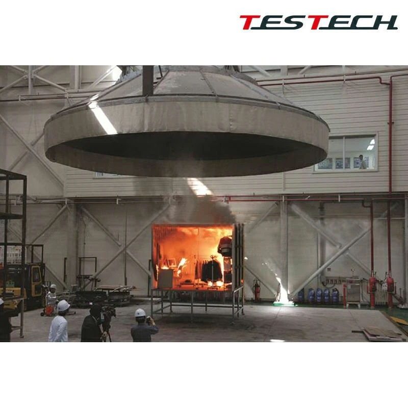
TESTech Instrument (Suzhou) Technologies is one of the leading manufacturers and suppliers of 10mw battery thermal release test system in China. Welcome to wholesale premium test equipment at competitive price from our factory. If you have any enquiry about quotation, please feel free to email us.
System Introduction
- This large heat release test system is developed with reference to ISO 9705, GB/T 20286-2006, GB/T 27904-2011, and GB/T 25207-2010 for large-scale battery fire heat release testing.
- The theoretical basis follows oxygen-consumption calorimetry, where generated heat is proportional to the consumed oxygen and each kilogram of oxygen corresponds to 13.1 MJ/kg of heat.
- Measured parameters include heat release, ignition time, oxygen consumption rate, CO generation rate, CO2 generation rate, gas flow, and smoke density release.
- The duct arrangement and sampling positions are designed with reference to foreign large heat release systems and airflow distribution studies in order to improve stability and accuracy.
- Built-in temperature sensors, gas flowmeters, gas samplers, and multi-stage filtered sampling lines help ensure long analyzer life.
- The Windows-based Labview system automatically acquires, analyzes, stores, and reports heat release rate, total heat release, smoke density, and other combustion-related values.

System Composition
- The system consists of the exhaust system, specimen fixtures, ignition system, smoke sampling and pretreatment system, gas analysis system, integrated control cabinet, computer analysis system, immersion lifting platform, and flue gas treatment system.
Exhaust System
- The exhaust system includes collection hood, guide duct, mixing duct, test flue section, exhaust section, and extension section.
- Collection hood and duct material: SUS304 stainless steel.
- Collection hood steel plate thickness: not less than 2 mm.
- 1 MW conical stainless steel collection hood opening: 3000 mm x 3000 mm.
- 10 MW conical stainless steel collection hood opening: 8000 mm x 8000 mm.
- 1 MW exhaust duct diameter: not less than 400 mm.
- 10 MW exhaust duct diameter: not less than 2000 mm.
- 1 MW straight exhaust duct length: not less than 6000 mm, fitted with motorized air valve.
- 10 MW straight exhaust duct length: not less than 30000 mm, fitted with motorized air valve.
- Exhaust duct steel plate thickness: not less than 2 mm.
- The gas mixer uses internal double-layer baffles to improve gas mixing effect and withstand temperatures not less than 1100 °C.
- Motorized fire-resistant fabric curtains are installed under the hood, sized 3 m x 3 m for 1 MW and 8 m x 8 m for 10 MW.
- The flue test section includes smoke gas sampler, smoke temperature measurement, airflow measurement, and photoelectric smoke density test system.
- An operating platform is provided at the sampling section of the flue for installation and maintenance access.
Air Velocity Control System
- The system consists of fan, frequency inverter, airflow probe, differential pressure gauge, and thermocouples.
- Three-phase variable-frequency fans ensure collection of all combustion smoke, with adjustable airflow during testing.
- 1 MW fan airflow capacity: 12000 m3/h.
- 10 MW fan airflow capacity: 200000 to 250000 m3/h, shared with the flue gas treatment end fan.
- Taiwan Delta inverter is used for precise duct airflow control.
- A bidirectional airflow probe is used for airflow pressure measurement.
- Imported U.S. differential pressure transmitter: range 0 to 2000 Pa, accuracy ±1% FS, hysteresis ±0.1% FS, maximum linear pressure 69 kPa, and 90% response time within 1 s.
- Imported OMEGA thermocouples monitor smoke temperature in real time with temperature accuracy 0.1 °C and wire diameter less than 0.25 mm.
- 1 MW configuration uses one thermocouple and 10 MW configuration uses nine thermocouples.
- Air velocity signals are automatically calculated and fed back for closed-loop control with stable airflow and strong anti-interference capability.
Smoke Sampling, Pretreatment, and Smoke Density Systems
- The smoke sampling and pretreatment system includes sampler, filters, cold trap, suction pump, drying tube, and flow controller.
- The stainless sampler is provided with sampling holes facing opposite to the gas flow direction.
- A three-stage filtration system with 0.2 um filtration accuracy is used to protect the gas analyzers.
- The compressor-type cold trap is controlled at 0 to 5 °C and keeps the sampled gas at 4 ±1 °C.
- Imported suction pump: flow 33 L/min, vacuum degree 700 mmHg, pressure 2.5 bar.
- The drying tube removes moisture and impurities from sampled gas.
- Imported flow controller supplies stable sample gas flow to the analyzers.
- Smoke density light source: imported 0.5 W He-Ne laser.
- Imported photoelectric receiver: wavelength range 350 to 1100 nm, peak response 0.65 A/W, maximum output current 100 mA, gain adjustment 70 dB, linearity not less than 99.8%, instability less than 0.1%, and receiving accuracy 0.1%.
- A one-touch five-level optical calibration system with imported Thorlabs filters is provided; deviation from theoretical values is controlled within 3%.
- A compensation photoelectric detection system is used to reduce interference caused by light source fluctuation.
Combustion Control, Heat Capacity, and Ignition Systems
- The combustion control system consists of gas piping, check valve, explosion-proof solenoid valve, mass flow controller, burner, and ignition controller.
- Stainless steel gas piping is used throughout the system.
- Sampling check valves, explosion-proof solenoid valves, and burner controllers with flame detection provide combustion safety.
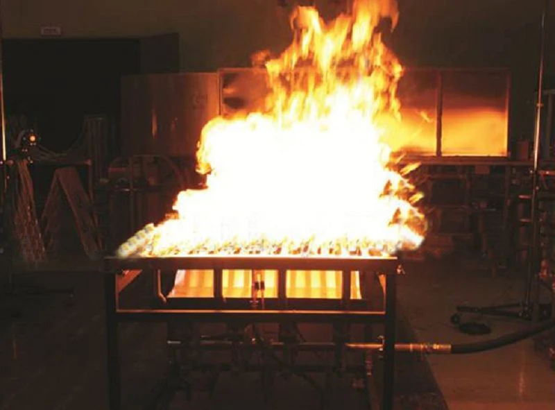
- Mass flow controllers and sandbox burners are used for stepwise heat release calibration.
- A dedicated heat capacity test method is included according to UL 9540A clause 9.2.12, including specific temperature measuring point layout and compensation calculations.
- The ignition source system uses high-voltage spark ignition with 60 kV and 23 mA output, ignition gap 6.4 mm, and five ignition source modules.
- The ignition source can operate at 10 s intervals or continuously and is positioned at specified vents and around them at 12.7 mm as described in the source content.
Common Gas Analysis, Hydrogen, FTIR, and Heat Flux Systems
- Paramagnetic oxygen analyzer: O2 range 0 to 25%, linear deviation not greater than 0.5% of range, repeatability not greater than 50 ppm, and T90 below 3.5 s.
- Infrared CO and CO2 analyzer: CO range 0 to 1%, CO2 range 0 to 10%, linear deviation not greater than 1% of range, and T90 below 2.5 s.
- Total hydrocarbon analyzer uses flame ionization detection, range 0 to 10000 ppm, and T90 below 3 s.
- Palladium-nickel hydrogen analyzer: working range 0.4 to 5%, measurement accuracy 0.3%, and RS232 plus 4-20 mA outputs.
- The auxiliary hydrogen analysis scheme provides internationally recognized support for low-concentration hydrogen detection and real-time online compensation for CO, CO2, CH4, and O2 interference.
- An additional Honeywell electrochemical hydrogen module is provided with measuring ranges 0 to 1000 ppm and 0 to 40000 ppm, maximum loads 2000 ppm and 40000 ppm, and resolution 10 ppm.
- The FTIR smoke toxicity analysis system measures toxic gas components online and uses a full heated path at 180 °C.
- FTIR spectral range: 500 to 5000 cm-1; resolution better than 1 cm-1; response time T90 less than 120 s.
- The FTIR gas cell uses stainless steel long-path design, 5 m to 9.8 m path length, gold-coated mirrors, and 180 °C heating.
- The battery combustion heat flux module uses Hukseflux heat flux meters in 0 to 20, 0 to 50, 0 to 100, and 0 to 200 kW/m2 ranges, with ten heat flux meters configured and support for up to sixteen in the cooling loop.
Calibration, Temperature Acquisition, Heating, Monitoring, and Control
- The module-level propane calibration system can perform 200 kW, 400 kW, and 600 kW heat release step calibration according to ISO 9705 concepts.
- The unit-level heptane calibration system can perform 1 MW, 2 MW, and 3 MW step calibration.
- The HIOKI temperature acquisition system provides 240 channels, 16-bit resolution, temperature range 0 to 1370 °C, and display resolution 0.1 °C.
- The battery heating system supports programmable temperature curves, target temperature 400 °C, and heating rate 4 to 7 °C/min with four-channel heating power supply.
- The movable fire wall uses black fire-resistant surface material and 16 ±1 mm gypsum board, sized to cover the hood opening.
- The monitoring system includes eight Hikvision cameras and one recorder, with 4K cameras and total storage of 16 TB, plus fireproof and explosion-resistant protection design.
- The standard control cabinet is equipped with a Dell computer, 19-inch LCD display, 16-bit acquisition modules, and Modbus digital communication.
- Labview software provides modular functions for parameter setting, analyzer calibration, optical calibration, heat release calibration, test operation, data analysis, and report printing.
- Optical system calibration uses one-touch five-level automatic calibration at 0%, 25%, 50%, 75%, and 100%, with automatic report generation.
- Control system power requirement: 100 to 230 V AC, 3 kVA; fan power requirement: 380 V AC, 220 kW.
Immersion Lifting Platform for Fire Suppression
- The immersion lifting platform is intended for thermal runaway testing of large battery samples such as single-cluster energy storage battery packs.
- Maximum compatible sample size on the platform is approximately 5000 mm x 2500 mm x 2000 mm, with single sample weight not exceeding 10 tons.
- Platform size: 5900 mm x 3900 mm.
- Adjustable immersion depth: 0 to minus 3000 mm relative to ground level.
- The lifting system uses hydraulic synchronized lifting with controlled displacement and guide design to avoid sway.
- The platform includes weighing capability to monitor mass before, during, and after combustion.
- The system supports remote and local manual control, with limit protection, buffer design, anti-drop protection on power loss, corrosion protection, and explosion and thermal shielding at critical locations.
- The water pit is designed for overflow control, cleaning, full drainage, and convenient removal of test residues.
- A plate-ring type load sensor is used to measure platform and specimen mass changes through the lifting connection.
Flue Gas Treatment System
- The flue gas treatment package includes design, manufacture, transport, installation, commissioning, training, and after-sales service.
- The total design treatment volume is two sets of 100000 m3/h, totaling 200000 m3/h.
- The recommended process route is spray tower plus wet electrostatic precipitator plus demister plus activated carbon adsorption.
- The spray tower dimensions are approximately 3400 mm diameter by 8500 mm height, with three spray layers and one demisting layer, using stainless steel construction and 11 kW pump.
- The high-voltage wet electrostatic precipitator is configured with PLC automatic control, 60 kV and 600 mA, automatic or manual washing, and anti-corrosion pump.
- The mist separation unit uses three-stage removal with two demisting layers and one dewatering layer.
- The activated carbon adsorption boxes use water-resistant honeycomb activated carbon with iodine value not less than 800 and approximately 600 boxes configured.
- Supporting equipment includes large carbon-steel ducts, 184 kW variable-frequency fans per line, outdoor inverter control cabinet, and approximately 15 m steel chimney with drainage and lightning protection.
- The system description includes detailed sections for fan selection, chimney, safety grounding, PLC control, commissioning, acceptance, and warranty service.
Specifications
|
Parameter |
Value |
|
Model |
Not provided |
|
Reference Standards |
UL 9540A; ISO 9705; GB/T 20286-2006; GB/T 27904-2011; GB/T 25207-2010 |
|
1 MW Hood Opening |
3000 mm x 3000 mm |
|
10 MW Hood Opening |
8000 mm x 8000 mm |
|
1 MW Exhaust Duct Diameter |
Not less than 400 mm |
|
10 MW Exhaust Duct Diameter |
Not less than 2000 mm |
|
1 MW Straight Duct Length |
Not less than 6000 mm |
|
10 MW Straight Duct Length |
Not less than 30000 mm |
|
1 MW Fabric Curtain |
3 m x 3 m |
|
10 MW Fabric Curtain |
8 m x 8 m |
|
1 MW Fan Airflow |
12000 m3/h |
|
10 MW Fan Airflow |
200000 to 250000 m3/h |
|
FTIR Resolution |
Better than 1 cm-1 |
|
Hydrogen Module Range |
0-1000 ppm and 0-40000 ppm |
|
Heat Flux Meter Quantity |
10 pcs |
|
Temperature Acquisition |
240 channels; 16-bit; 0 to 1370 °C |
|
Ignition Source Modules |
5 pcs |
|
Platform Size |
5900 mm x 3900 mm |
|
Platform Max Load |
10 tons |
|
Control System Power |
100 to 230 V AC; 3 kVA |
|
Fan Power |
380 V AC; 220 kW |
|
Flue Gas Treatment Capacity |
200000 m3/h total |
Hot Tags: 10mw battery thermal release test system, China 10mw battery thermal release test system manufacturers, suppliers, factory


